Decoding of the first line info block
Pixel | 0 | 1 | 2 | 3 | 4 | 5 | 6 | 7 | 8 | 9 | 10 | 11 | 12 | 13 | 14 | 15 | 16 | 17 | 18 | 19 | 20 | 21 | 22 | 23 |
|---|---|---|---|---|---|---|---|---|---|---|---|---|---|---|---|---|---|---|---|---|---|---|---|---|
Line 0 | Marker | Serial number | Marker | Image count | Exposure time | Marker | Line time | Encoder clocks | Error code | Time stamp | Marker | |||||||||||||
Serial number
"Serial number" shows the serial number of the camera. The serial number consists of two parts. The first part is the type-specific part and equal for all cameras of the same type. This information can be used to check the camera type. The second part is the camera-specific serial number and different for each camera.
The first 2 digits represent the camera family (eg. 40231)
allPIXAevo | eg. 40231
allPIXAevo - SN digit 3 e.g. 40231 | Camera type |
|---|---|
0 | allPIXAevo 1 |
1 | allPIXAevo 2 |
allPIXAevo - SN digit 4 e.g. 40231 | Interface type |
|---|---|
0 | Dual10GigE |
1 | DualSingle10GigE |
2 | Single10GigE |
3 | 4x CxP12 |
allPIXAevo - SN digit 4 e.g. 40231 | Sensor resolution |
|---|---|
0 | 15K |
1 | 10K |
3 | 8K |
9 | 16K |
allPIXAneo | e.g. 41136
allPIXAneo - SN digit 4 e.g. 41136 | Camera type |
|---|---|
0 | mono |
1 | color - VIS |
3 | color - NIR |
allPIXAneo - SN digit 4 e.g. 41136 | Interface type |
|---|---|
3 | 2x CxP12 |
4 | nBase-T |
5 | nBase-T without PoE |
allPIXAneo - SN digit 4 e.g. 41136 | Sensor resolution |
|---|---|
2 | 2K |
4 | 4K |
6 | 6K |
8 | 8K |
9 | 16K |
Structure
The serial number consists of two parts.
SN first part | SN second part | ||
|---|---|---|---|
Byte 3 | Byte 2 | Byte 1 | Byte 0 |
Px1 | Px2 | Px3 | Px4 |
Decoding
The decoding of the serial number is:
The first part of the serial number S1 = Px1 × 256 + Px2
The second part of the serial number S2 = Px3 × 256 + Px4
Example
S1 = 156 × 256 + 64 = 40000
S2 = 0 × 256 + 157 = 157
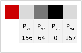
Example: decoding of SN: 40000-00157
Image count
"Image count" is a counter that increments by 1 for each new image. This information can be used to ensure that all images are processed/saved.
Structure
Image count | |
|---|---|
Byte 1 | Byte 0 |
Px6 | Px7 |
Decoding
The decoding of the image count is:
Ic = Px6 × 256 + Px7
Example
Ic = 1 × 256 + 120 = 376
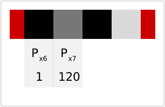
Example: image count 376
Exposure time
This information can be used to read out the exposure time in us of the image.
Structure
Exposure time clocks | |
|---|---|
Byte 1 | Byte 0 |
Px8 | Px9 |
Decoding
The decoding of the exposure time is:
Et = (Px8 × 256 + Px9) / fa
fa (10k, 15k) = 50 Mhz
fa (8k) = 80 Mhz
Example
Et = (5 × 256 + 220) / 50 = 50 µs
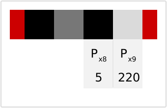
Example: Decoding of exposure time
Line time
This information represents the line time of the line that contains the first line infoblock.
Structure
Line time clocks | ||
|---|---|---|
Byte 2 | Byte 1 | Byte 0 |
Px11 | Px12 | Px13 |
Decoding
The decoding of the Line time is:
Lt = (Px11 × 216 + Px12 × 28 + Px13) / 100
Example
Lt = (0 × 216 + 21 × 28 + 124) / 100 = 55 µs
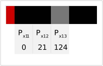
Example: Decoding of line time
Encoder clocks
This information is a counter that counts the single encoder signals. For a 2-channel encoder, the counter also counts backward for inverse transport direction. This information can be used to reference the position of the image to the absolute position of the transport process. The counter starts at 0 at the camera start and can not be reset.
Structure
Encoder clocks | |||
|---|---|---|---|
Byte 3 | Byte 2 | Byte 1 | Byte 0 |
Px14 | Px15 | Px16 | Px17 |
Decoding
The decoding of the encoder clocks is:
Ec = Px14 × 232 + Px15 × 216 + Px16 × 28 + Px17
Time stamp
This is a timestamp which starts at 0 at the camera start. The resolution is 250us, after ~18h there is a counter overflow, the timer starts at 0 again.
Structure
Time [s] | Time [¼ ms] | |
|---|---|---|
Byte 2 | Byte 1 | Byte 0 |
Px19 | Px20 | Px21 |
Decoding
The decoding of the time stamp is:
Ts = (Px19 × 216 + Px20 × 28 + Px21) / 4