Decoding of the each line info block
Pixel | 0 | 1 | 2 | 3 | 4 | 5 | 6 | 7 | 8 | 9 |
|---|---|---|---|---|---|---|---|---|---|---|
Red | Marker | Error code | Speed2high | Encoder clocks | Next line position | Time stamp | Unsupported | Unsupported | Unsupported | Marker |
Green | Continuous line count | Line count | Line time | |||||||
Blue |
Continuous line count
This counter increments by 1 for each row of the image. The counter continues counting for new images and is not reset. It can be used to detect missing image information.
Structure
Continuous line count | ||
|---|---|---|
– | Byte 1 | Byte 0 |
Px0Red | Px0Green | Px0Blue |
Decoding
The decoding of the continuous line count is:
Clc = Px0Green × 256 + Px0Blue
Example
Clc = 217 × 256 + 127 = 55679
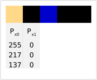
Example: Decoding of continuous line count
Line count
This counter increments by 1 for each row of the image. The counter starts counting at 0 for each image. It can be used to detect missing image information.
Structure
Line count | ||
|---|---|---|
– | Byte 1 | Byte 0 |
Px1Red | Px1Green | Px1Blue |
Decoding
The decoding of the line count is
Lc = Px1Green × 256 + Px1Blue
Example
Lc = 0 × 256 + 0 = 0
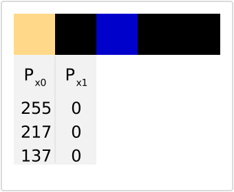
Example: Decoding of line count
Speed too high
This information can be used to check if the speed of the line trigger signal is too high for the camera. In this case, the camera switches to freerun and acquires with the maximum possible speed. This state must be avoided because the transport resolution of the image is not constant. If the flag is “True” for some lines there are the following options to avoid this issue.
The speed too high state can be caused by two parameters
Exposure time (Exposure time ≥ Line time - 2us offset)
Compare the exposure time with the info block information “line time“ to check if the exposure time is the limiting factor.Interface speed
To avoid the speed too high state there are multiple options.
Reduce the transport speed if possible.
If the info block information “line time“ oscillates heavily check the electrical connection or try to stabilize the mechanical transportation process.
If the exposure time is the limiting factor reduce the exposure time.
If the interface speed is the limiting factor, increase the interface speed is possible (Use more CXP lanes or a faster CXP type / Use dual 10GigE)
Structure
Speed2high | – |
|---|---|
Bit 7 | Bit 6 – Bit 0 |
Px2Red | |
Line time
This information represents the line time. For an operation without a line trigger, this variable is constant and equal to the camera parameter line time. If the camera is triggered with a line trigger this information can be used to check the signal/mechanical transport quality.
If the signal oscillates very heavily with a high frequency the electrical connection is not OK.
.png "grafik(1).png")
Small oscillations (for example +-20%) are most probably mechanical vibrations in the transport process.
These effects are typical for:Belt drives
Conveyor belts
Low-quality linear stages for scans with a high resolution.
Structure
Line time clocks | |||
|---|---|---|---|
Bit 7 – Bit 4 | Bit 3 – Bit 0 | Byte 1 | Byte 0 |
Px2Red | Px2Green | Px2Blue | |
Decoding
The decoding of the line time is:
Lt = (Px2Red × 216 + Px2Green × 28 + Px2Blue) / 100
Example
Lt = (0 × 216 + 21 × 28 + 124) / 100 = 55 µs
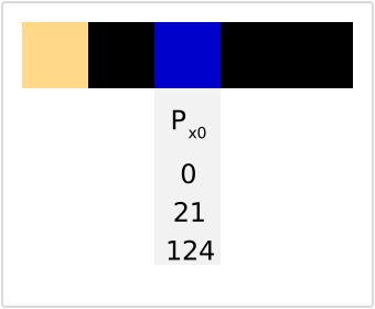
Example: Decoding of line time
Encoder clocks
Structure
Encoder clocks | ||
|---|---|---|
Byte 2 | Byte 1 | Byte 0 |
Px3Red | Px3Green | Px3Blue |
Decoding
The decoding of the encoder clocks is:
Ec = Px3Red × 216 + Px3Green × 28 + Px3Blue
Next line trigger position
Structure
Next lt pos raw | ||
|---|---|---|
Byte 2 | Byte 1 | Byte 0 |
Px4Red | Px4Green | Px4Blue |
Decoding
The decoding of the encoder clocks is:
Nlp = (Px4Red × 216 + Px4Green × 28 + Px4Blue) / 256
Time stamp
Structure
Time [s] | Time [¼ ms] | |
|---|---|---|
Byte 2 | Byte 1 | Byte 0 |
Px5Red | Px5Green | Px5Blue |
Decoding
The decoding of the time stamp is:
Ts = (Px5Red × 216 + Px5Green × 28 + Px5Blue) / 4