Camera specifications
General | |||
Model | allPIXA neo 6k CXP Mono | allPIXA neo 6k CXP Color | allPIXA neo 6k CXP Color-NIR |
Product code | CP000660-06K-44-M1-A1 | CP000660-06K-44-C1-A1 | CP000660-06K-44-C2-A1 |
Availability | Available | ||
Sensor | |||
Sensor type | Line scan 2D | ||
Chroma | Mono | Color + Mono | Color + NIR |
Spectrum | Visible | ||
Spectral range | 400 nm – 960 nm | ||
Resolution | 6144 × 1 | 6144 × 4 lines | 6144 × 4 lines |
Sensor architecture | CMOS (SI) | ||
Sensor Size / Image circle | 31 mm | ||
Pixel size | 5 µm × 5 µm | ||
Pixel formats / Data format / Output color space | |||
Data format | 1 × 8/10/12 Bit mono | 3 × 8/10/12 Bit color or 1 × 8/10/12 Bit mono or 4 × 8/10/12 RGB + Mono | 3 × 8/10/12 Bit color or 1 × 8/10/12 Bit mono or 4 × 8/10/12 RGB + Mono |
Sensor bit depth (ADC) | 10-bit | ||
Video output | 2 x CoaxPress 2.0 | ||
Imaging performance | |||
Quantum efficiency (529 nm) | |||
Quantum efficiency (850 nm) | |||
Full well capacity | |||
Timing and gain | |||
Max. line rate (single-line) | 240 kHz | ||
Max. line rate (tri-linear) | 80 kHz | 80 kHz | |
Max. line rate (quad-linear) |
| 60 kHz | 60 kHz |
Exposure time | |||
Gain | |||
I/O’s and Power | |||
Non-isolated lines (I/O’s) | 1 BiDir LVCMOS 3V3 | ||
Specific non-isolated lines (I/O’s) | 2 RS422-In*1 (or 2 SE-In 3, 3V…24V) 2 RS422-In/out (or 2 SE-In 3, 3V…24V or 2 SE-OUT 3V3) 2 RS422-OUT (or 4BiDir LVCMOS 3V3) 1 Fan 5V (or UART for Debug) | ||
Opto-isolated lines(I/O’s) | 0 | ||
Power supply | Power over CXP or digital I/O port | ||
Power consumption | External: 12 W | ||
Operating conditions | |||
Operating temperature (housing) | 0 °C – 60 °C; 32 °F – 140 °F | ||
Mechanical properties | |||
Body dimensions (L x W x H) | 62 mm × 62 mm × 62 mm | ||
Filter / Protection glass | |||
IP class (ingress protection) | IP50 | ||
Shock and vibration tests | |||
Lens mount | M42 × 1 mm / F-Mount, TFL | ||
Weight / Mass | 0,35 kg | ||
On-board memory on FPGA | |||
Image buffer (RMA) | 512MB | ||
Non-volatile memory (Flash) | 1 Gbit | ||
User data memory | No separate memory space | ||
Interface for image transfer | |||
Digital interface / Video output | 2 x CXP-12 Micro-BNC | ||
Interface connector | Micro-BNC | ||
Vision standard | CoaxPress | ||
Temperature during transport and storage | -20 °C – +85 °C; -4 °F – +185 °F | ||
Certifications | CE, RoHS | ||
General ambient conditions | |||
Transport | IEC 721-3-3:IE33 | ||
Operation | IEC 721-3-3:IE21 | ||
Storage | IEC 721-3-3:IE11 | ||
Camera features
Image control | |
Binning | Digital |
Color transformation | Ye |
Brightness and Contrast | Yes |
Exposure modes | Manual |
PRNU | Yes |
DSNU | Yes |
Gain modes | Manual Auto |
Gamma | Yes |
LUT (look-up table) | Yes |
Mirror Images | Yes |
ROI (region of interest) | Yes |
White balance mode | Manual Auto |
Camera control | |
Acquisition Line Rate | Yes |
Action commands (Trigger over CXP) | Yes |
Temperature monitoring | Yes |
Trigger mods / sync | Freerun Internal Software trigger External trigger Line trigger Frame trigger Encoder |
User sets | Yes |
Master Slave | Yes |
Flash (Multi field imaging) | Yes |
Sensor temperature control | |
Temperature specific events | Yes |
Temperature status indicator | Yes |
Line scan sensor
Sensor pixel arrangement
 Left: Sensor line spacing and pixel arrangement of the 6k sensor
Right: Sensor line spacing and pixel arrangement of the 6k sensor with NIR
Spectral sensitivity
 Measured relative sensitivity of the color and the mono sensor
 Measured relative spectral sensitivity of the 6k sensor with NIR
Sensor alignment and orientation
![]() Alignment and orientation of the 6k sensor: Color + Mono
Alignment and orientation of the 6k sensor: Color + Mono
Mechanical dimensions
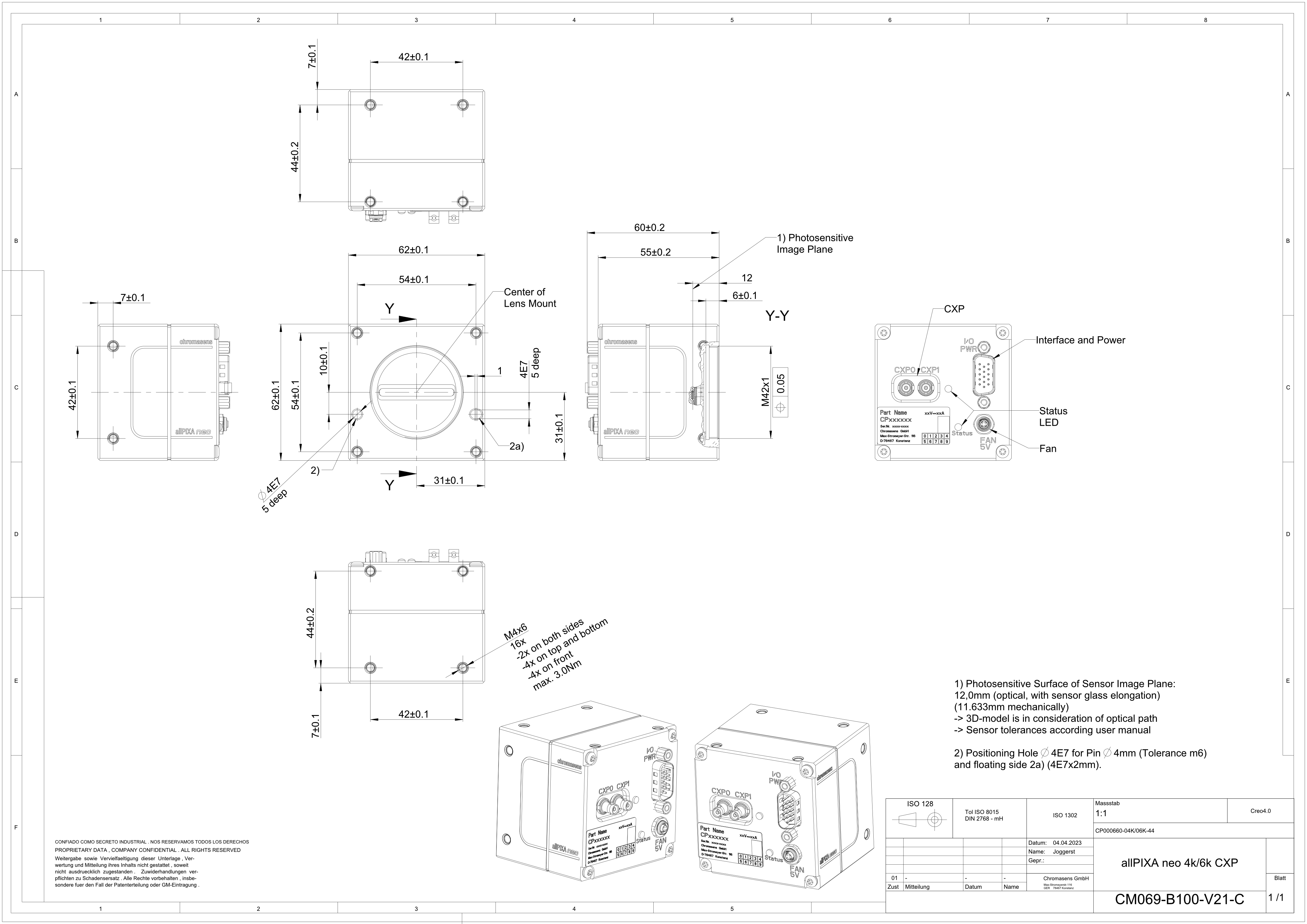 Dimensional drawing of the allPIXA neo 4k/6k CXP
Interface specification
 | |||
| 1 | Video output port (2 × CoaXPress 2.0) and power supply | 2 | Digital I/O port and power supply |
| 3 | Connector for additional fan | 4 | Status LED |
Line rate
| Configuration (8 bit) | Line rate |
|---|---|
| Mono | 240 kHz |
| RGB | 80 kHz |
| RGB + Mono (NIR) | 60 kHz |
Power supply
You can either use Power over CoaXPress (PoC) or the power supply of the external digital I/O port.
Digital I/O port
The following connector is required for the digital I/O port:
- 15 pin HD D-Sub (female)
 Pin allocation D-Sub connector (male) of the camera
You can configure the digital I/O port as RS422 or as single-ended input or output. It is also possible to configure one output as RS422 and the other output as single-ended.
RS422 configuration
| Pin | Line definition for RS422 configuration | Signal RS422 | Configuration proposal |
|---|---|---|---|
| 1 | Line 1 | In1+ | Encoder Source A, Line Start |
| 2 | In1– | Encoder Source A\, Line Start\ | |
| 3 | Line 2 | In2+ | Encoder Source B, Fame Start, Frame Active |
| 4 | In2– | Encoder Source B\, Fame Start\, Frame Active\ | |
| 5 | GND (Signals) | Signals Ground | |
| 6 | Line 3 | In3+/Out3+ | Encoder Source A, Fame Start, Frame Active, Line Start, User Output3+ |
| 7 | In3–/Out3– | Encoder Source A\, Fame Start\, Frame Active\, Line Start\, User Output3- | |
| 8 | Line 4 | In4+/Out4+ | Encoder Source A, Fame Start, Frame Active, Line Start, User Output4+, MS-In+ |
| 9 | In4–/Out4– | Encoder Source A\, Fame Start\, Frame Active\, Line Start\, User Output4-, MS-In- | |
| 10 | GND (PWR) | Camera Power Ground | |
| 11 | Line 5 | Out5+ | User Output5+, MS-Out+ |
| 12 | Out5– | User Output5-, MS-Out- | |
| 13 | Line 6 | Out6+ | User Output6+ |
| 14 | User Output6- | ||
| 15 | Vcc (PWR) | Camera Power DC +12 V – +24 V |
Single-Ended (SE) configuration
The input threshold voltage can be configured globally to 3.3 V, 5 V, 12 V and 24 V. The Maximum input voltage is 28 V. The set voltage level is then active for all single ended inputs and outputs.
| Pin | Line definition for Single-Ended configuration | Signal Single-Ended | Configuration proposal |
|---|---|---|---|
| 1 | Line 1 | In1 (3.3 V, 5 V, 12 V, 24 V) | Encoder Source A, Line Start |
| 2 | -- | -- | -- |
| 3 | Line 2 | In2 (3.3 V, 5 V, 12 V, 24 V) | Encoder Source B, Fame Start, Frame Active |
| 4 | -- | -- | -- |
| 5 | GND (Signals) | Signals Ground | |
| 6 | Line 3 | In3 (3.3 V, 5 V, 12 V, 24 V) Out3 (3.3 V) | Encoder Source A, Fame Start, Frame Active, Line Start, User Output3+ |
| 7 | -- | -- | -- |
| 8 | Line 4 | In4 (3.3 V, 5 V, 12 V,24 V) Out4 (3.3 V) | Encoder Source A, Fame Start, Frame Active, Line Start, User Output4+ |
| 9 | -- | -- | -- |
| 10 | GND (PWR) | Camera Power Ground | |
| 11 | Line 5 | In5 (3.3 V) Out5 (3.3 V) | LED Flash Out 3, User Output5 |
| 12 | Line 7 | In7 (3.3 V) Out7 (3.3 V) | LED Flash Out 2, User Output7 |
| 13 | Line 6 | In6 (3.3 V) Out6 (3.3 V) | LED Flash Out 0, User Output6 |
| 14 | Line 8 | In8 (3.3 V) Out8 (3.3 V) | LED Flash Out 1, User Output8 |
| 15 | Vcc (PWR) | Camera Power DC +12 V – +24 V |
LED status indicator
| Color code | Behaviour | Description |
|---|---|---|
 | Off | No power supply or the input voltage is out of range. |
 | Solid orange | The system is booting. |
 | Flash_1_1red | The device is powered but not connected (not applicable to a device reliant on PoCXP power). |
 | AlternateFlash_12_5 green/orange; shown for a minimum of 1s even if connection detection is faster | The Connection detection is in progress, PoCXP is active. |
 | Flash_12_5 orange; shown for a minimum of 1s even if connection detection is faster | The Connection detection is in progress, PoCXP is not in use. |
 | AlternateFlash_0_5 red/green | The device/host is incompatible, PoCXP is active. |
| AlternateFlash_0_5 red/orange | The device/host is incompatible, PoCXP is not in use. |
 | Solid red | PoCXP is over-current (host only). |
 | Solid green | The device/host is connected, but no data is transferred. |
 | Flash_1_ orange | The device/host is connected, waiting for event (e.g. trigger). |
 | Flash_12_5 green | The device/host is connected, data is being transferred. |
 | 500ms red pulse | Error during data transfer (e.g. CRC error, single-bit error) is detected. In case of multiple errors, there shall be at least two green Flash_12_5 pulses, before the next error is indicated. |
 | AlternateFlash_0_5 green/orange | A connection test packet is being sent. |
 | AlternateFlash_0_5 red/green/orange | The compliance test mode is enabled (device only). |
 | Flash_12_5 red | A system error (e.g. internal error) ocurred. |