GigE 接口
10 GigE 连接器允许使用(直接连接)长度达 30 m (10BASE-T) 的铜缆。必须使用最低规格为 CAT6a 的电缆。
网络适配器
要建立 10 GigE 连接,必须在 PC 上安装并配置具有 10 GigE RJ45 输入的网络适配器。GCT 文档中介绍了网络适配器的安装。有关更多信息,请参阅 Installation GigE。
有关经过测试的网络适配器和收发器的更多信息,请参阅 Tested Network adapters and Transceivers.
布线
 | .png) WARNING WARNING |
| Electric shock due to improper connection to a power supply. | |
| Use a 12 V – 24 V DC power supply. When using the digital I/O port as a power supply ensure the correct polarity. |
连接视频输出端口。
连接数字 I/O 端口。
选项 1:以太网供电 (PoE)
1. Plug the Ethernet cable into the Power/PoE port (PoEOUT) of the PoE injector and into the video output port (RJ45) of your camera.
2. Connect another Ethernet cable to the Ethernet/data (DataIN) port of the injector and your network card.
选项 2:数字 I/O 端口的电源
To set up the wiring refer to section Digital I/O port.
Note the permitted input voltages:
Nominal | Minimum | Maximum | |
|---|---|---|---|
Permitted voltages | 24 V | 12 V | 28 V |
CXP 接口
该接口允许您连接两根 CXP 电缆。需要用于相机的微型 BNC(用于 CXP12)连接器和用于图像采集卡的合适连接器。最大电缆长度为 35 m。
图像采集卡
要建立 CXP 连接,必须在 PC 上安装并配置图像采集卡。请参阅图像采集卡的手册。
有关测试的图像采集卡的详细信息,请参阅 Tested frame grabbers。
布线
| WARNING |
| Electric shock due to improper connection to a power supply. | |
| Use a 12 V – 24 V DC power supply. When using the digital I/O port as a power supply ensure the correct polarity. |
连接视频输出端口。
连接数字 I/O 端口。
选项 1:CoaXPress 供电 (PoC)
要使用 power-over-CXP 功能,需要两个连接。
选项 2:数字 I/O 端口的电源
To set up the wiring refer to section Digital I/O port.
Note the permitted input voltages:
Nominal | Minimum | Maximum | |
|---|---|---|---|
Permitted voltages | 24 V | 12 V | 28 V |
数字 I/O 端口
The following connector is required for the digital I/O port:
- 15 pin HD D-Sub (female)
 Pin allocation D-Sub connector (male) of the camera
You can configure the digital I/O port as RS422 or as single-ended input or output. It is also possible to configure one output as RS422 and the other output as single-ended.
RS422 configuration
| Pin | Line definition for RS422 configuration | Signal RS422 | Configuration proposal |
|---|---|---|---|
| 1 | Line 1 | In1+ | Encoder Source A, Line Start |
| 2 | In1– | Encoder Source A\, Line Start\ | |
| 3 | Line 2 | In2+ | Encoder Source B, Fame Start, Frame Active |
| 4 | In2– | Encoder Source B\, Fame Start\, Frame Active\ | |
| 5 | GND (Signals) | Signals Ground | |
| 6 | Line 3 | In3+/Out3+ | Encoder Source A, Fame Start, Frame Active, Line Start, User Output3+ |
| 7 | In3–/Out3– | Encoder Source A\, Fame Start\, Frame Active\, Line Start\, User Output3- | |
| 8 | Line 4 | In4+/Out4+ | Encoder Source A, Fame Start, Frame Active, Line Start, User Output4+, MS-In+ |
| 9 | In4–/Out4– | Encoder Source A\, Fame Start\, Frame Active\, Line Start\, User Output4-, MS-In- | |
| 10 | GND (PWR) | Camera Power Ground | |
| 11 | Line 5 | Out5+ | User Output5+, MS-Out+ |
| 12 | Out5– | User Output5-, MS-Out- | |
| 13 | Line 6 | Out6+ | User Output6+ |
| 14 | User Output6- | ||
| 15 | Vcc (PWR) | Camera Power DC +12 V – +24 V |
Single-Ended (SE) configuration
The input threshold voltage can be configured globally to 3.3 V, 5 V, 12 V and 24 V. The Maximum input voltage is 28 V. The set voltage level is then active for all single ended inputs and outputs.
| Pin | Line definition for Single-Ended configuration | Signal Single-Ended | Configuration proposal |
|---|---|---|---|
| 1 | Line 1 | In1 (3.3 V, 5 V, 12 V, 24 V) | Encoder Source A, Line Start |
| 2 | -- | -- | -- |
| 3 | Line 2 | In2 (3.3 V, 5 V, 12 V, 24 V) | Encoder Source B, Fame Start, Frame Active |
| 4 | -- | -- | -- |
| 5 | GND (Signals) | Signals Ground | |
| 6 | Line 3 | In3 (3.3 V, 5 V, 12 V, 24 V) Out3 (3.3 V) | Encoder Source A, Fame Start, Frame Active, Line Start, User Output3+ |
| 7 | -- | -- | -- |
| 8 | Line 4 | In4 (3.3 V, 5 V, 12 V,24 V) Out4 (3.3 V) | Encoder Source A, Fame Start, Frame Active, Line Start, User Output4+ |
| 9 | -- | -- | -- |
| 10 | GND (PWR) | Camera Power Ground | |
| 11 | Line 5 | In5 (3.3 V) Out5 (3.3 V) | LED Flash Out 3, User Output5 |
| 12 | Line 7 | In7 (3.3 V) Out7 (3.3 V) | LED Flash Out 2, User Output7 |
| 13 | Line 6 | In6 (3.3 V) Out6 (3.3 V) | LED Flash Out 0, User Output6 |
| 14 | Line 8 | In8 (3.3 V) Out8 (3.3 V) | LED Flash Out 1, User Output8 |
| 15 | Vcc (PWR) | Camera Power DC +12 V – +24 V |
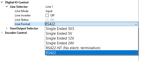
配置 I/O
可以在 GCT 中配置 IO 端口。
1. 在 GCT 中连接并打开相机 | |
2. 导航至 相机功能、数字 IO 控制 | |
3. 在 Line Selector 中选择 Line | |
4. 打开下拉菜单并更改 Line Format |
|
电路图
RS422 配置
 External circuit: RS422 device
单端配置
 External circuit: Optocoupler
 External circuit: TTL or CMOS logic gate
电源
To set up the wiring refer to section Digital I/O port.
Note the permitted input voltages:
Nominal | Minimum | Maximum | |
|---|---|---|---|
Permitted voltages | 24 V | 12 V | 28 V |
输入电流为 0.5 A @ 24 V。